|
| |
|
EFIE
Electronic Fuel Injection
Enhancer
|
| So, you are thinking of using Hydrogen and
Oxygen as an additive to your gasoline engine, and you are wondering if you
need to invest in an EFIE device. That is not an easy question to answer. In the past, fuel savers would not work when
applied to fuel systems that use oxygen sensor feedback circuits. These systems
were designed to prevent efficient combustion, by lowering and controlling the air mixture
of the engine from 14.7 parts to 14.5 parts of air for each part of fuel!
This was done to reduce Carbon Monoxide and NOX emissions in the engines
exhaust, and to make your engine use more gas. The EPA then made auto
manufacturers add expensive Catalytic Converters to the exhaust systems in
order to get rid of the unburned fuel. To date, this is one of the biggest
Scams ever pulled on the public. We fell for it, hook, line, and sinker. To
beat all, it is computer controlled. If enough hydrocarbons are not measured
in the exhaust, the computer sends more gasoline. This is the number one
reason why most Fuel Saving Devices Do Not Work.
Increasing the combustion efficiency of the engine changes the percentage of
oxygen in the exhaust because the engine uses less fuel for the same volume
of air and the engine produces less carbon
monoxide and oxides of Nitrogen. Oh, we can't have that (so says the EPA).
The increased oxygen content in the exhaust is read by the computer to be
a lean mixture in the engine. As a result, the computer then adds extra fuel
to bring the pollution back to normal. In other words, when the computer
sees extra oxygen in the exhaust, it sends enough fuel to maintain a 14.5
parts air to 1 part fuel ratio. When the computer sees less oxygen in the
exhaust, it backs off on the fuel to maintain a 14.5 to 1 fuel ratio. The EFIE's function is to modify the oxygen sensor's output-signal
to the computer - by adding a
floating voltage; so the computer will not see the extra oxygen.
If you plan on using Hydrogen and Oxygen as an additive, one way or
another, the air fuel ration will have to be dealt with, if you want better
fuel mileage. Hydrogen as an additive works. Oxygen as an additive works.
They both provide better, more complete, combustion of the fuel. They both
decrease harmful exhaust emissions. Period. It is a proven fact.
It is the
computer controlled Emissions Control System that reverses the positive
benefits of HHO.
The EPA has been slowly passing tamper laws. It is unlawful to tamper
with the Emission Control Sensors. These laws are going to be enforced,
starting January 1, 2011. But
there are no laws against reprogramming an Emissions Control System as long
as the EPA standards are met or improved. That is the reason I chose the
Volo Chip for my Ford modification. The chip replaces the ECM settings, in
order to change and maintain better Air Fuel mixtures, based on driving
conditions. If you have a 1996 through 2009 vehicle with an OBD-2
Emissions Control System, then the Volo may be good choice for a lot of
vehicles. I say may, because it is turning out that it is not the solution
for a lot of vehicles. It falls short. The ECM works around it somehow. If your vehicle is year 1987 through 1995, you probably have an
OBD-1 Emissions Control System. OBD-1 systems usually need an EFIE; but not
always. Some respond by injecting the HHO in front of the MAF sensor, so
that the HHO must pass through the MAF sensor (if they have a MAF). Some of these vehicles accept HHO without any changes,
just by resetting the computer; most do not. Reset the computer by
disconnecting the battery for a few minutes. It causes the computer to
relearn the fuel mixture. |
| |
|
 Which EFIE do I
need?
Which EFIE do I
need?
Sensor Request Form (find out what sensors you have and what Type they
are)
About Oxygen Sensors
Oxygen Sensors, How to Diagnose and Replace
OBD1 Vehicles, pre- 1996
HHO Shortcuts
|
| |
|
|
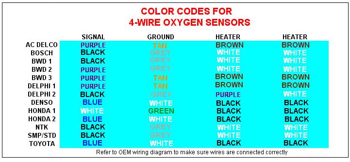
5 Types of Oxygen Sensors |
| |
|
|
Unheated Thimble-type O2
Sensors (LS)
Bosch introduced this design in 1976 for feedback fuel control on automotive
engines. The zirconia ceramic "thimble" is encased in a protective tube
which extends into the exhaust manifold. Slots in the protective tube allow
hot exhaust gases to reach the thimble. Reference outside air for the
interior of the thimble comes from a hole in the sensor shell, or through
the wiring connector. Unheated O2 sensors rely only on the heat of the
exhaust gases to reach operating temperature, therefore they might cool off
while the engine is idling and revert back to a fixed air/fuel ratio
setting. This type of sensor generally has a single wire connector, though
some have two.
Heated Thimble-type O2 Sensors
(LSH)
Introduced by Bosch in 1982, this sensor adds a heater element to the
original design so that the sensor achieves operating temperature in 30-60
seconds, instead of being heated by exhaust gases. It has a separate
electric circuit for the heater, so look for 3 or 4 wire connectors to
distinguish this unit. The heater reduces cold start emissions, as well as
prevents the sensor from cooling off at idle.
Heated Titania-type O2 Sensors
Titania sensors use a different type of ceramic and instead of generating a
voltage signal that changes with the air/fuel ratio, the sensor's electrical
resistance changes. The resistance is less than 1000 ohms when the air/fuel
ratio is rich, and more than 20,000 ohms when the air/fuel ratio is lean.
The ECU provides a base reference voltage and then monitors the sensor
return voltage as the sensor's resistance changes. Titania O2 sensors are
used on less than 1% of O2 sensor-equipped vehicles:
-
86-'93 Nissan 3.0L trucks
-
'91-'94 Nissan 3.0L Maxima,
2.0L Sentra
-
'87-'90 Jeep Cherokee,
Wrangler, and Eagle Summit
Heated Planar-type O2 Sensors
(LSF)
Introduced by Bosch in 1997, this O2 sensors uses a laminated flat strip
of conductive ceramic, electrodes, insulation, and heater. This sensor is
smaller and lighter, and more difficult to contaminate. The new heater uses
less electricity and brings the sensor to the proper temperature in 10
seconds. Outside reference air is supplied by a small port in the center of
the ceramic strip where the 4 electrical wires connect. By model year 2004,
planar O2 sensors are expected to account for 30% of all O2 sensor
applications and by 2008, for up to 75%. The following list shows the
inclusion of more and more models:
-
1998: VW 2.0L New Beetle
-
1999: Cadillac Catera, Saturn
3.0L LS, VW 2.0L Jetta
-
2000: All Audis exc. A4 1.8L
turbo and A6 2.8L; California Dodge 2.0L Neon; Ford 4.0L and 5.0L
Explorer; Ford 2.5L LEV Ranger; Ford 3.8L Windstar; MBZ 3.2L ML320 and
4.3L ML430; Mercury 4.0L & 5.0L Mountaineer; Saab 2.0L & 2.3L; and all
VW and Volvo models
-
2001: Porsche 911 3.6L Turbo;
all MBZ models exc. SL500 and SL600
-
2002: All Audis, All Dodge
Neons, all Ford F-Series trucks (4.2L, 4.6L, 5.4L), all Ford Ranger
trucks, Mazda B-Series pickups (2.5L, 3.0L & 4.0L), all MBZ models and
Saturn 3.0L SUV
Heated Wide-Band O2 Sensors
(LSU) (from the November 2001 Bosch Reporter)
The newest O2 sensor technology from Bosch builds
upon the planar design and adds the ability to actually measure the air/fuel
ratio directly for the first time. Instead of switching back and forth like
all previous sensor designs, the new wide-band O2 sensor produces a signal
that is directly proportional to the air/fuel ratio.
The wide-band sensor uses a "dual
sensing element" that combines the Nernst effect cell in the planar design
with an additional "oxygen pump" layer and "diffusion gap" on the same strip
of ceramic. The result is a sensor element that can precisely measure
air/fuel ratios from very rich (10:1) to extremely lean (straight air). This
allows the engine computer to use an entirely different operating strategy
to control the air/fuel ratio. Instead of switching the air/fuel ratio back
and forth from rich to lean to create an average balanced mixture, it can
simply add or subtract fuel as needed to maintain a steady ratio of 14.7:1.
Like a zirconia thimble or
planar-type sensor, the wide-band sensor produces a low-voltage signal when
the air/fuel ratio goes lean, and a high-voltage signal when the mixture is
rich. But instead of switching abruptly, it produces a gradual change in the
voltage that increases or decreases in proportion to the relative richness
or leanness of the air/fuel ratio. So, at a perfectly balanced air/fuel
ratio or 14.7:1, a wide-band O2 sensor will produce a steady 450 mv. If the
mixture goes a little richer or a little leaner, the sensor's output voltage
will only change a small amount instead of rising or dropping dramatically.
Another difference in the
wide-band O2 sensor is the heater circuit. Like a planar sensor, it is
printed on the ceramic strip. But the heater circuit is pulse-width
modulated to maintain a consistent operating temperature of 1292 to 1472
degrees F. the sensor takes about 20 seconds to reach operating temperature.
Reference:
http://tayloredge.com/reference/Science/oxygensensor2.pdf
Note: There are two types of narrowband sensors
- Zirconia and Titania. Titania is used in Jeeps and off-road vehicles,
especially. Please read this link to understand the difference
http://www.ngk.com/sparkplug411.asp?kw=Titania&mfid=1
|
|
Bosch Wideband Oxygen Sensors Precisely Measure Air/Fuel
Ratios |
| |
|
Wideband Oxygen Sensors
As engine management and on-board diagnostic systems continue to
evolve, so too do the oxygen sensors that monitor the air/fuel mixture. The
latest generation of "wideband" oxygen sensors from Robert Bosch are
smarter, faster, more durable and capable of precisely measuring exact
air/fuel ratios - a feat that was impossible with earlier generations of O2
sensors.
Traditionally, oxygen sensors have
been used to monitor the level of unburned oxygen in the exhaust.The amount
of oxygen that's left in the exhaust following combustion is a good
indicator of the relative richness or leanness of the fuel mixture.
When air and gasoline are mixed
together and ignited, the chemical reaction requires a certain amount of air
to completely burn all of the fuel. The exact amount is 14.7 lbs of air for
every pound of fuel. This is called the "stoichiometric" air/fuel ratio.
It's also referred to the the Greek letter "lambda."
When lambda equals one, you have a
14.7:1 stoichiometric air/fuel ratio and ideal combustion. When the air/fuel
ratio is greater than 14.7:1, lambda also will be greater than one and the
engine will have a lean mixture.
Lean mixtures improve fuel economy
but also cause a sharp rise in oxides of nitrogen (NOX). If the mixture goes
too lean, it may not ignite at all causing "lean misfire" and a huge
increase in unburned hydrocarbon (HC) emissions. This can cause rough idle,
hard starting and stalling, and may even damage the catalytic converter.
Lean mixtures also increase the risk of spark knock (detonation) when the
engine is under load.
When the air/fuel ratio is less
than 14.7:1, lambda also is less than one and the engine has a rich fuel
mixture. A rich fuel mixture is necessary when a cold engine is first
started, and additional fuel is needed when the engine is under load. But
rich mixtures cause a sharp increase in carbon monoxide (CO) emissions.
When the relative proportions of
air and fuel are "just right," the mixture burns clearly and produces the
fewest emissions. The trick is balancing the mixture as driving conditions,
temperatures and loads are constantly changing. That's where oxygen sensors
come in.
By monitoring the level of
unburned oxygen in the exhaust, the sensor(s) tell the engine computer when
the fuel mixture is lean (too much oxygen) or rich (too much fuel). To
compensate, the computer adjusts the fuel mixture by adding more fuel when
the mixture is lean, or using less fuel when it is rich.
That's the basic feedback fuel
control loop in a nutshell. The trouble is, conventional oxygen
sensors give on a rich-lean indication. They can't tell the computer the
exact air/fuel ratio. When the air/fuel ratio is perfectly balanced, a
convention O2 sensor produces a signal of about 0.45 volts (450 millivolts).
When the fuel mixture goes rich, even just a little bit, the O2 sensor's
voltage output shoots up quickly to its maximum output of close to 0.9
volts. Conversely, when the fuel mixture goes lean, the sensor's output
voltage drops to 0.1 volts.
Every time the oxygen sensor's
output jumps or drops, the engine computer responds by decreasing or
increasing the amount of fuel that is delivered. This rapid flip-flopping
back and forth allows the feedback fuel control system to maintain a
more-or-less balanced mixture, on average. But this tried-and-true approach
that has worked so well thus far isn't accurate enough to meet the latest
emissions requirements.
The new NLEV (national low
emission vehicle) standards plus California's LEV (low emission vehicle),
ULEV (ultra low emission vehicle) and SULEV (super ultra low emission
vehicle) standards all require very precise control over the air/fuel ratio.
Reducing cold emissions when the engine is first started is absolutely
critical to meeting these standards. But conventional oxygen sensors (even
with heaters) warm up too slowly to provide the degree of accuracy needed to
meet cold emissions. They also lack the ability to tell the PCM the exact
air/fuel ratio, something that is becoming increasingly necessary as
advanced fuel control strategies are introduced. A simple rich
The Wideband Air/Fuel Sensor
The newest generation of oxygen sensors
are being called "wideband" lambda sensors or "air/fuel ratio sensors"
because that's exactly what they do. They provide a precise indication of
the exact air/fuel ratio, and over a much broader range of mixtures - all
the way from 0.7 lambda (11:1 air/fuel ratio) to straight air!
The Bosch LSU 4 wideband oxygen
sensor is a 5-wire sensor that reads oxygen in much the same way as a
traditional oxygen sensor. but it uses the latest "planar" construction with
a special two-part sensing element to measure how much oxygen is in the
exhaust.
In 1997, Bosch developed a new
type of construction for oxygen sensors that uses a flat ceramic zirconia
element rather than a thimble. It's called a "planar" sensor because the
sensor element is a flat strip of ceramic that is only 1.5mm thick. The
electrodes, conductive layer of ceramic, insulation and heater are laminated
together on a single strip. The new design works the same as the
thimble-type zirconia sensors, but the "thick-film" construction makes it
smaller and lighter, and more resistant to contamination. The new heater
element also requires less electrical power and brings the sensor up to
operating temperature in only 10 seconds.
In creating the new LSU 4 wideband
air/fuel ratio sensor, Bosch combined the oxygen-sensing "Nernst" cell from
the planar sensor with an "oxygen pump" to create a device that can actually
measure air/fuel ratios. Here's how it works:
The Nernst cell still senses
oxygen in the same way that a conventional thimble-type O2 sensor does. When
there's a difference in oxygen levels across the zirconium dioxide sensor
element, current flows from one side to the other and produces a voltage.
But, as we said earlier, this isn't good enough because it gives only a
gross rich-lean indication of the air/fuel mixture.
To get the added precision, the
oxygen pump uses a heated cathode and anode to pull some oxygen from the
exhaust into a "diffusion" gap between the two components. The Nernst cell
and oxygen pump are wired together in such a way that it takes a certain
amount of current to maintain a balanced oxygen level in the diffusion gap.
And guess what? The amount of current required to maintain this balance is
directly proportional to the oxygen level in the exhaust. This gives the
engine computer the precise air/fuel measurements it needs to meet the new
emission requirements.
The wideband oxygen sensor
receives a reference voltage from the engine computer and generates a signal
current that varies according to the fuel mixture.
When the air/fuel mixture is
perfectly balanced at 14.7:1 (the stoichiometric ratio and lambda equals 2),
the sensor produces no output current. When the air/fuel mixture is rich,
the sensor produces a "negative" current that goes from zero to about 2.0
milliamps when lambda is 0.7 and the air/fuel ratio is near 11:1.
When the air/fuel mixture is lean,
the sensor produces a "positive" current that goes from zero up to 1.5
milliamps as the mixture becomes almost air.
The Bosch LSU 4 wideband oxygen
sensor has a response time of less than 100 milliseconds to changes in the
air/fuel mixture, and reaches operating temperature of 700 to 800 degree
Centigrade (1,400 degree F) within 20 seconds or less using its internal
heater. This is nearly twice the operating temperature of a conventional
oxygen sensor.
Other Uses
Many performance engine builders and tuners have discovered the benefits of
using the wideband oxygen sensor technology to monitor air/fuel ratios.
Being able to see the actual air/fuel ratio at any given instant in time
allows the fuel mixture to be fine-tuned and adjusted on the fly - something
which previously could only be done on a dynamometer using expensive
equipment.
The air/fuel ratio is critical
with high performance, turbocharged and supercharged engines to make power
and to keep the engine from leaning out at high rpm and boost pressures. If
the mixture leans out, it can send the engine into self-destructing
detonation.
Reference:
http://tayloredge.com/reference/Science/oxygensensor3.pdf |
| |
|
Bosch Wideband Oxygen Sensor Diagnostics |
| |
|
Diagnostics
Because of the internal circuitry used in
a wideband oxygen sensor, you can't hook up a voltmeter or oscilloscope to
read the sensor's output directly. A wideband O2 sensor produces a current
signal that varies not only in amplitude but direction. That makes it quite
different from a conventional oxygen sensor that produces a voltage signal
that bounces back and forth between 0.1 and 0.9 volts.
The only way you can currently
diagnose a wideband oxygen sensor is through the vehicle's on-board
diagnostic system using a scan tool.
You can use the scan tool to read
the actual air/fuel ratio, and to check the sensor's response to changes
that should cause a change in the air/fuel ratio. Opening the throttle wide,
for example, traditionally causes a sudden and brief lean condition followed
by a richer mixture as the computer compensates. But with the new control
strategies made possible with wideband O2 sensors, the air/fuel ratio
remains steady when the throttle is snapped open.
The diagnostic strategies for
wideband O2 sensors vary from one vehicle manufacturer to another but, as a
rule, you'll get an oxygen sensor code if the sensor reads out of its normal
range, if the readings don't make sense to the computer (should indicate
lean when lean conditions exist, etc.) or if the heater circuit fails.
One thing to keep in mind about
wideband O2 sensors is that they can be fooled in the same way as a
conventional oxygen sensor by air leaks between the exhaust manifold and
head, and by misfires that allow unburned oxygen to pass through into the
exhaust. Either will cause the sensor to indicate a false lean condition
which, in turn, will cause the computer to make the engine run rich.
Other Wideband Sensors
It's important not to confuse Bosch wideband O2 sensors with those produced
by other OEM suppliers. With some other wideband O2 sensors (such as those
used in 1996 and newer Toyotas, for example), a scan tool will display a
"simulated" voltage reading between 0 and 1 volt. The actual voltage output
from the sensor is much higher, but the computer is calibrated to divide the
sensor's actual output by 5 to comply with OBD II regulations that require a
display reading of 0 to 1 volts (these regulations have since been revised
to allow the actual voltage to be displayed.)
Sensor Replacement
Bosch wideband oxygen sensors are designed for an operational life of
100,000 miles. Replacement should be needed only if the sensor has failed
due to unusual operating conditions, physical damage, or contamination.
Blowing a head gasket can allow silicon to enter the exhaust and contaminate
the sensor. Oil burning can allow phosphorus to enter the exhaust and
contaminate the sensor. If replacement is necessary, use the same type of
wideband sensor as the original.
Reference:
http://tayloredge.com/reference/Science/oxygensensor3.pdf |
| |
| |
|
|
|
| |
|
|
EFIE's |
|
 Tuning 101 AFR Control Center
If you
want to obtain the largest mileage gains possible...from any HHO Generator, you
must modify the signals from 4 sensor groups. Just doing the O2 Sensors,
with an EFIE, will not get it done on most vehicles.
This is the only product on the market that can get it done.
|
| |
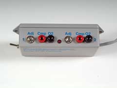
Dual EFIE (Analog)
An Electronic Fuel Injection Enhancer is used to adjust the signal from
the oxygen sensor before they get to the engine's computer to compensate for
an increase in fuel efficiency brought about by another fuel efficiency
device. The Dual version handles two oxygen sensor.
|
|
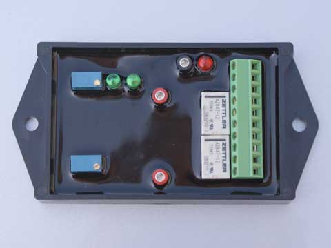 Digital EFIE
The Quad Digital EFIE Basic is the newest member of our family of EFIE's.
Digital EFIE's allow much leaner settings on vehicles than other types of
EFIE. We recommend Digital EFIE's for all narrow band oxygen sensors that are
upstream of the catalytic converter. Note, that the Quad EFIE uses a pair of
analog EFIE's for the downstream sensors. |
|
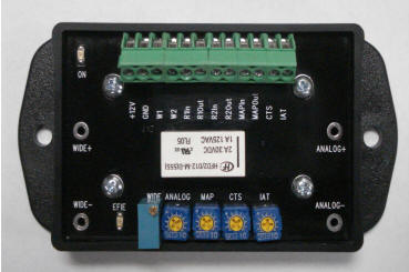
 Frequency MAP /
MAF Enhancer
Frequency MAP /
MAF EnhancerOur new frequency based MAP/MAF enhancer
is the first universal MAP/MAF Sensor Enhancer. It can be used for
devices that output a frequency to the computer, or devices that send an
analog voltage signal. |
| |
|
| |
|
 Eagle-research EFIE - sold from their web site
EFIE Kit, unassembled - eagle-research.com
EFIE, Assembled - eagle-research.com
Adjusting the EFIE (video)
Important:
Regardless of what you read elsewhere, this EFIE works on ALL types of
oxygen sensors, including Titania (varying resistance) sensors, A/F sensors
and wideband sensors. |
| |
|
| |
| |
|
|
|
EFIE Documentation
/Instructions/Tuning/etc. |
|
|
EFIE Circuit Schematic and Parts
List |
|
|
Dealing with the Vehicle Computer
(EFIE & MAP/MAF) |
| |
Page Last Edited
-
04/03/2022 |
|
