"Requires 1 additional gasket per water compartment"
Multiple Cell Stacks require Reversing the position of the gasket hole
slots, for each stack. In other words, one stack will have "cut-out" on
the left, the other stack - on the right. It is necessary in order to
keep the gases separated (collecting in the right channel).
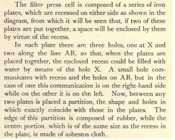
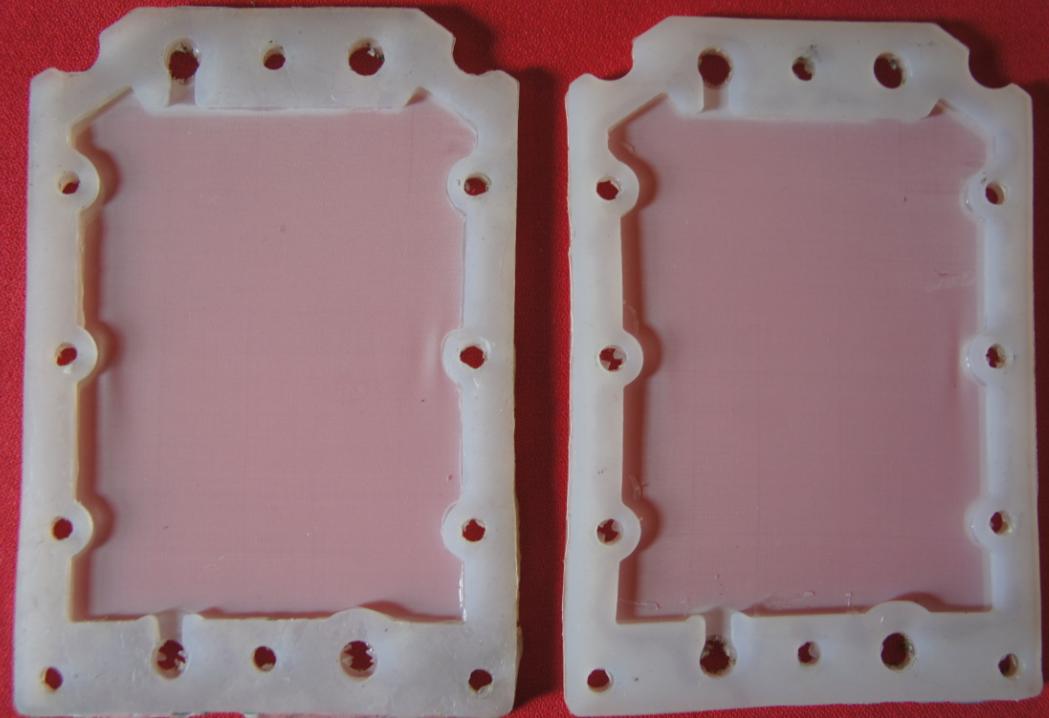
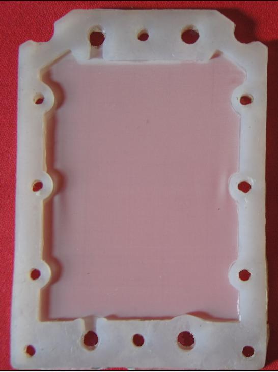
Assembled Gaskets & Membrane
How it Works
Hopefully
this information will help advance Dry Cell Technology. A few
experimenters are using Nylon Monofilament Mesh to divide water chambers
into 2 areas; one for hydrogen and one for oxygen. To get an
idea of how this is done, watch the videos below. Notice that they
are using 2 gaskets between each set of plates. The Nylon Mesh is
inserted between the two gaskets (Red line in the picture above). The mesh keeps the Hydrogen on one side, and the Oxygen on the other side.
There are special slots in the gaskets for channeling the gases to separate
gas output ports. Instead of HHO coming out of one port, Hydrogen and
Oxygen have their own ports. Watch the videos and you will get a better
idea of how this works. The method was used by in the early 1900's.
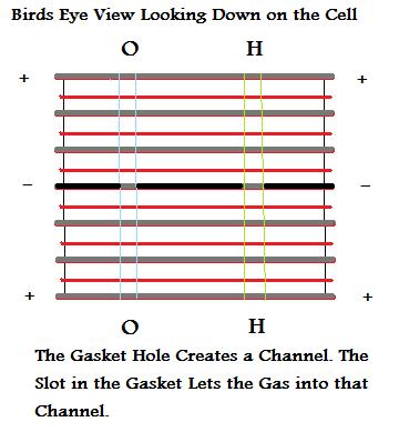
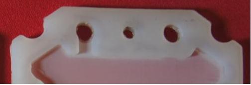
Gas Outlet Ports
Notice the
gas outlet port on the left. There is a slot cut in the gasket so that
the gases on that side of the nylon membrane can escape through the
hole. The other side of that hole looks like the hole on the far right.
The gasket seals that hole so that gases can not enter on the other side
(mix). The membrane separates the gases. The slots in the gasket pass or
block the gases; keeping them separated. By alternating the slots, gases
can be collected and kept separated. This method can be traced back to,
before, the year 1919.
I have tested this method of separation, and it
does separate the gases quite well. It also allows the water to refill
the chambers. It easily passes through the membrane. It is also
important to note that backpressure can cause the gases to mix. That
means, we need to make it as easy as possible for the gases to escape
through the holes, and also through their respective bubblers. Pressures
should be the same in both bubblers. That means the water levels need to
be the same. So, it may be necessary to equalize the water levels via a
hose between them.
In the picture above, there is a flaw in the gasket shape. It is the
small area at the top, to the left and right of the holes. Gases can
collect there; you don't want that. If they collect there, it is
possible for them to leak through the membrane material and mix on the
opposite side of the membrane. We are trying to avoid mixing.
Each of
the Outlet Holes is dedicated to only allowing one gas to pass through
it. As the gases are made, they rise to the top; the membrane guides
them. They are blocked from entering one hole, and allowed to enter the
other. This process is repeated as additional electrode plates are
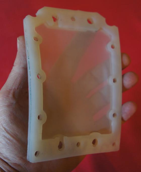
added. In the next picture that follows, I am holding a gasket assembly.
It consists of the membrane sandwiched between 2 identically cut
gaskets. The gaskets are turned to face opposite directions. One faces
to the front, the other to the back, so that the "Cut out Slots" are on
opposite ends. If you build and assemble your gaskets, individually,
like this, then it is almost impossible to make a mistake when you start
assembling the layers of plates. Keep the tops on top and the bottoms on
the bottom. The sides will always match up.
Membrane Materials being used:
Polyester Monofilament Mesh (works with Sodium Hydroxide, NaOH)
Nylon Monofilament Mesh (works with Potassium Hydroxide, KOH)
Silkscreen Mesh, T165
Uncoated Rip-Stop Nylon
300 cross thread count , per inch, is recommended (or higher).
About mesh size: Mesh
size is measured by how many threads of mesh there are crossing per
square inch. For instance, a 165 mesh screen has 165 threads
crossing per square inch. The higher the mesh count, the finer the
threads and holes in the screen.
300
cross-counts are recommended, but any count
higher than that will work; 400,500; etc.
The mesh forms a thin wall that allows the water to pass
through it, but not the bubbles. The H and O ions pass
through the water, cross the membrane, and form the gas on
the electrode plate they are attracted to (positive or
negative). The Hydrogen stays on the negative side of the
membrane wall, and the oxygen stays on the positive side.
The mesh is a dividing wall; it forms/separates two
chambers. The gases rise to the top of their respective side
of the chamber, and collect at the top. They escape through
the hole in the electrode plate; so, it is very important to
make holes in the mesh that match up with the holes in the
plates. Cut out holes for the water and for the gas. If you
do not, back pressure will be created, and that could cause
the gases to mix. The gases take the path of least
resistance.
Mesh material can be obtained from Fabric shops,
Silkscreen shops, Ebay.com, amozon.com, Tent repair
shops; etc.
1 Millimeter = 1 000 Micrometers Millimeter is a metric unit and equal to one thousandth of a
meter. Spelled as millimetre in most of the countries. Used widely
to measure small distances in engineering and machining. The
abbreviation is "mm".
Micrometer is a metric unit and usually used for precise
measurement of small distances in engineering and machining. The
abbreviation is "µm".
Gasket Material:
High Temperature Neoprene Rubber
EPDM Rubber
Silicone
End Plate Material:
3/4 inch HDPE
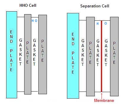
HHO Separation Cells
Global Ecological Solutions - HHO Separation Cells:
Global Ecological Solutions product web page
(Exceptional quality
and workmanship)
"Guaranteed Not To Leak Water"
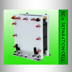
SC-1 For 12 Volt DC Systems.
* Capable of producing 1 LPM of Hydrogen at 24 Amps.
* Operate Continuous at 22 Amps / 0.9LPM of Hydrogen
"Click on the Picture"
for more details
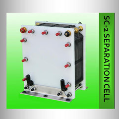
SC-2 is for 12 & 24 VDC Systems.
* Capable of producing 2 LPM of Hydrogen at 24 Amps/24vdc
Designed to Operate Continuous at 22 Amps / 1.8 LPM/24vdc
* Capable of producing 2 LPM of Hydrogen at 48 Amps/12vdc
Designed to Operate Continuous at 44 Amps / 1.8
LPM/12vdc
"Click on the Picture"
for more details
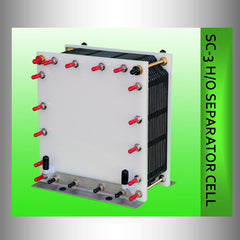
SC-3 is for 12 & 24 VDC Systems.
* Capable of producing 3 LPM of Hydrogen at 36 Amps/24vdc
Designed to Operate Continuous at 38 Amps / 3.2 LPM
* Capable of producing 3 LPM of Hydrogen at 72 Amps/12vdc
Designed to Operate Continuous at 76 Amps/12vdc
* They overstate the LPM for Hydrogen. They say 1.9 LPM at 30 amps.
The cell is not capable of even making that much "HHO" at 30 amps, much
less Hydrogen.
* I can not speak for their quality of product or
reliability.
Available at their web site
Hydro Bullet - Separation Cell
* I do not have any information on the quality or reliability of
their products But all looks well. They have 24 hour customer support.
* They overstate the LPM of Hydrogen; so do not expect to
get what they say.
Example: They say their 6 plate HHO cell produces 600 MLPM of HHO @ 10
amps,
They say their 6 plate Separation cell produces 700 MLPM of Hydrogen @
10 amps.
* They only use 1 external water fill port, but the
water ingeniously gets divided behind the End Plate.
* They do a good job of Separating the hydrogen and
oxygen.
Available at their web site
Hydro-gas - HydroGenesis Separation Cells
* I do not have any information on this cell. The web site is very
lacking.
* No product information is furnished, what so ever.
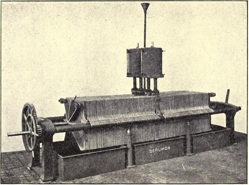
A large number of commercial cells put the anode and cathode
comparatively close together, but, in order to obtain reasonably high
purity in the gaseous products, a porous partition was placed between
the electrodes: this, like increasing the distance between the plates,
creates a certain amount of resistance, but it has one advantage of the
latter procedure in that it makes for compactness, which is very
desirable in any plant and particularly so in the case of electrolytic
ones, as one of the greatest objections to their use is the floor space
which they occupy. If you study this picture, you
see that Dry Cell technology is nothing new.
The membranes go between the neutral and active plates,
they aid to keep the gases separate with help of the special gaskets.
They are very accurately laser cut for a number of reasons, they have to
fit correctly between the gaskets, and the mating holes need to be
accurate too. The edges must not go past the gasket edges or leaks will
occur, so the membranes are made 2mm smaller than the gaskets (3mm). It
is near impossible to cut these by hand successfully.
The cell
does not claim to separate 100% but the concept looks promising. I think
the hydrogen is going to speed its way to the top...and out. While, the
slow oxygen...which is an accumulating bubble with a membrane...slowly
follows the contours of the mesh divider.
It may be possible to use
this mesh in a bubbler. First, the HHO should pass through the mesh,
which would break up the gases into smaller bubbles. Those bubbles
would rise in a chamber with another layer of mesh. I think the oxygen
gases, which are heavy and slow moving, would linger underneath the
mesh, and the hydrogen would pass through it...since it is moving at 20
feet per second. You would need a barb fitting just under the mesh to
allow the oxygen gas to exit the bubbler. Plus, a fitting farther above
the mesh for the hydrogen. I learned from Joe, of joecells, that the two
gases will not pass through the same hole at the same time. With that in
mind, it may also work with two output hoses at the top of the bubbler.
There are other theories for separation of the gases. One is to use
magnetic fields to help direct the gases out. I know this helps move HHO
up and out of tube cells. Stan Meyer used opposite high voltage
potential fields. Positive repelled the Hydrogen and attracted the
Oxygen.
Another
Example:
Video
plays off-site
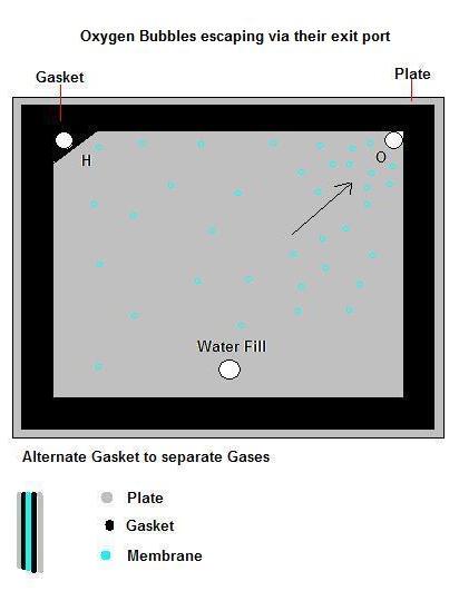
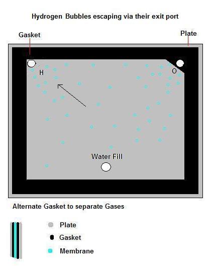
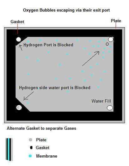
My concept of
the idea:
The membrane is sandwiched between two gaskets.
Hydrogen is collected on one side of the membrane, and oxygen on the
other; the two gases are kept separated as they climb the membrane
wall..
You will need two top holes for the gases to exit.
Each hole gets obstructed from the gas producing surface of the opposite plate.
Reverse the gasket, on the opposite side of the membrane.
Keep alternating the gaskets this way.
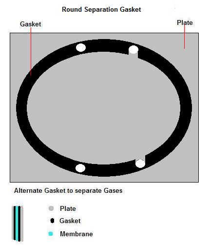
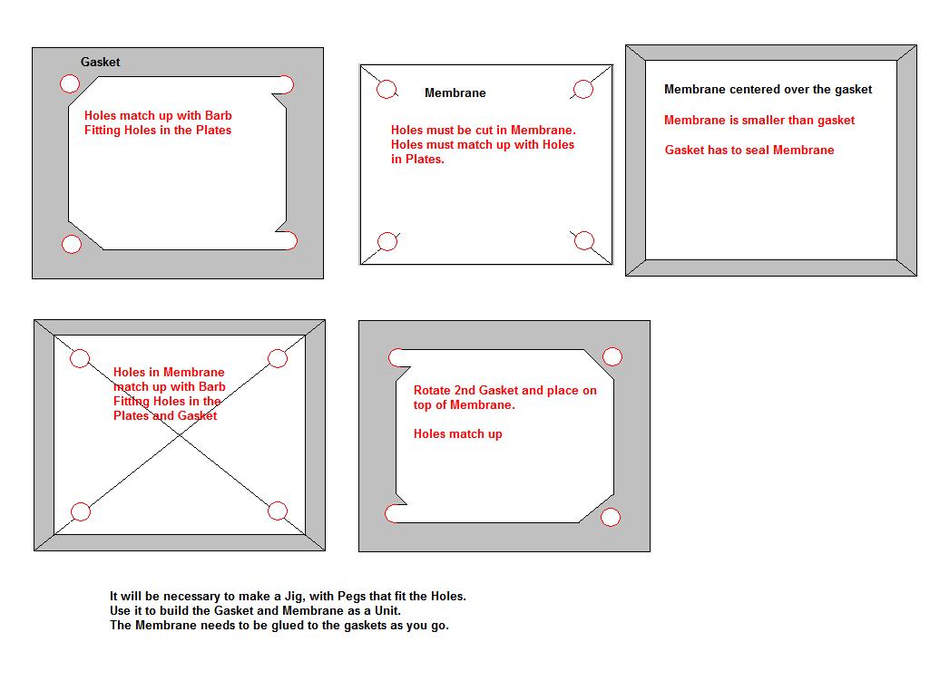
The drawings below depict the general idea. Gasket shape and design
are left up to you.
Below, is a version using 2 water fills; one for each gas. It would allow
better circulation.
Separation Gasket & Membrane Assembled.
Each consists of 2 gaskets with a membrane sandwiched and glued between them.
These were boiled for 5 minutes after the glue dried. The heat tightens the membrane by shrinking it slightly.
This process makes the gasket easy to handle.
It also makes the cell easier to assemble.
Ceramic Separation Membrane Development :
The process requires high pressurization of the
gases.

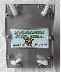
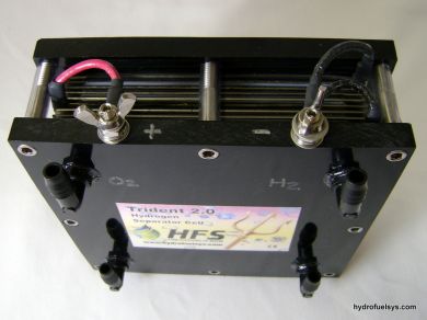 Hydrogen Fuel Systems - HHO Separation Cell
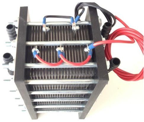 Hydro Bullet - Separation Cell
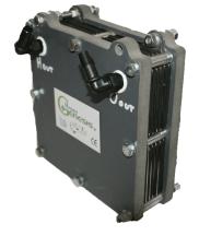 Hydro-gas - HydroGenesis Separation Cells