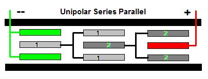
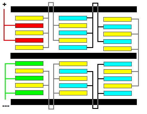
Using the diagram above, I am going to explain the path that
amperage takes, as it passes through the Unipolar Cell. For
simplicity, try to imagine amperage as a fluid. Amperage from the battery
divides equally across the 2 Negative plates as it travels
towards the Positive .... on the other end of the cell. There are 2
Neutral Plate Groups in between that it must pass through. The amperage collected on each
Negative plate is attracted across the water to the
more
positive 1 Neutral Group. The amperage combines on the first
neutral and then splits equally on the last two 1 Neutral Group
plates. From there amperage travels across the water to
the more positive 2 Neutral Group plate. The amperage combines
on that neutral then splits in half as it travels to the last 2
Neutrals. From there amperage travels across the water and
collects on the Positive plate, then proceeds on to the battery. The circuit acts as a Series Cell.
The Neutral Groups are between negative and positive electrodes.
They create their own isolated water areas, the same as
traditional Bipolar Series Cells.
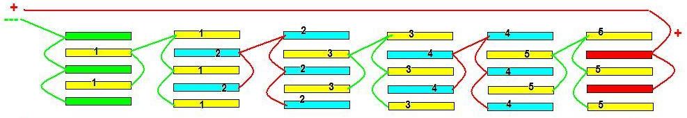
The best way to understand this particular Unipolar configuration is to
look at it as a 4 plate 2 Stack Series Parallel Cell;
- N N + N N -
The difference being Series neutrals
are Bipolar; meaning they are more negative on one side and more
positive on one side, where as Unipolar plate is only one polarity,
either more positive or more negative. This Unipolar
configuration creates - N N + N
N - it does
it by creating Paths. There are 2 Paths for amperage to
take....across 2 sets of Neutrals.
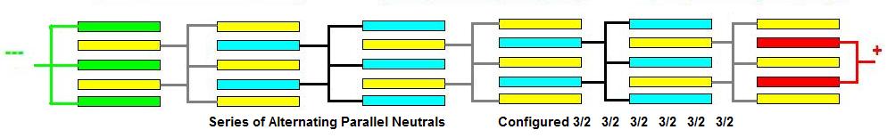
This Unipolar Series Parallel configuration uses
9 plates to configure 6 water areas by way of 2 Paths/Stacks. A
2 stack Bipolar Series Parallel configuration can accomplish this with 7
plates.
If another plate is added to each of the Columns
in this Unipolar configuration, it accomplishes the same thing
as adding another Stack to a Bipolar Series Parallel configuration.
If another Neutral Group is added to this
Unipolar configuration, it accomplishes the same thing as adding
a Neutral Plate to each Stack in a Bipolar Series Parallel
configuration. Adding Neutral Groups increases HHO production
the same way that adding Neutral plates does in a Bipolar Series
Parallel configuration.
Now that you know the path amperage takes, lets look at the relationship
of amperage and HHO production. Faraday tells us that the gas is made
between 2 apposing plates, of different potential. He tells us that 1
ampere makes 0.0003689 CFM of HHO; converting that to metric ...would be
10.44 ML per minute. That is the amount made between two apposing
plates. There is no mention of Size of the plates; none what so ever.
However, there is mentioned that 1 square inch of surface area can
efficiently handle 0.54 amps. If Current Density exceeds 0.54 amps per
square inch, we make a lot more heat in the process of making more HHO.
What you need to take from this is that it is not plate size that makes
more gas; It is the number of water compartments (cells). The more of
them you add, the more gas you make. The more of them you put the same
amperage through, the higher your MMW will be.Two Unipolar plates can
make no more HHO per square inch than two Bipolar plates can make per
square inch. However, minor details in construction can help you or hurt
you; regardless of polarity type. When I look at Unipolar, I see the
same potential for current leakage, from plate to plate, as I see in
Bipolar. If the edges are exposed to water, they are just as vulnerable
to current leakage as Bipolar plates. If holes are in the plates, they
are just as vulnerable to current leakage ....if the edges are exposed.
A well known HHO forum mentor/advisor is saying current flows around
Unipolar plates and passes through Bipolar plates. That is nonsense.
Amperage does not pass through metal; it passes around the surface,
perpendicular to the surface. That forum also states that Bipolar does
not have Neutrals. Nonsense; if it does not have an electrical
connection on it, and current passes across it, what do you call it? A
rose is a rose is a rose, no matter what you name it.
Are there benefits to Unipolar Cells? Some say there are.
- For instance, they operate cooler. Well yes, they can operate
cooler if each Stack/Column does not share water compartments. The
same can be accomplished with multiple stack Bipolar Cells, but most
builders do not do this. They also say Unipolar operates cooler
because of the number of plate Paths. Again, the same can be
accomplished with Bipolar Cells by adding more Stacks; builders
choose not to do so because it requires more amperage in order to
get more HHO gains.
- Unipolar produces more HHO. Well not so fast. The potential may
be there for efficient Unipolar designs, but a like system can be
built using Bipolar designs....which will use less plates and
produce equal amounts of gas......That is, if you measure them with
the same set of meters.
- Unipolar has been observed to produce bubbles on the back sides
of End Plates when they are exposed to water. I should mention, that
the same thing happens with Bipolar Plates. The magnetic field is
polarized, is it not? Electrons flow towards more positive
potentials, while liberated ions are attracted towards opposite
potentials. It is reasonable to assume there are liberated ions
throughout the entire embodiment of water.
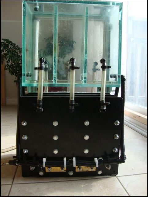
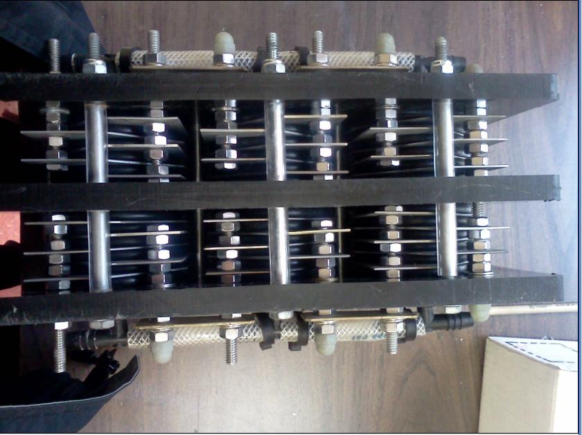
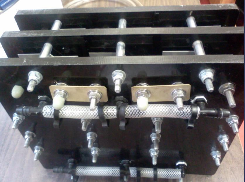
Igor's Unipolar cell is based on a construction
technique that came to him in a dream. It made sense; he understood it,
so he built it. It worked great and it looks great. What more can one
ask for....Right? Well, now he asks, how can I make it better. |